
PE Racing
Brake Analysis - Optimise your brake package PE-005-2004
Brake Analysis - Optimise your brake package PE-005-2004
Couldn't load pickup availability
Improve your performance and results by engineering preferred setups to suit your race car.
PE Racing offers this Engineering service to help you optimise the Brake system.
This service provides insight into the overall braking performance to suit your specific vehicle & how to optimise your setup & maximise your braking G's.
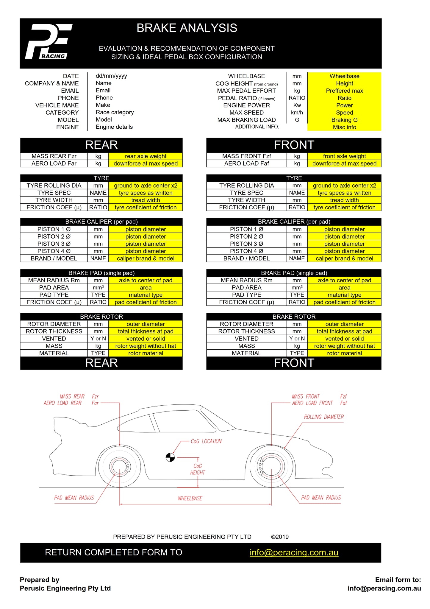
Download Brake Analysis Form (found in downloads, or link below) & return to by email to info@peracing.com.au
Purchasing 1 unit of this service is usually enough with a fully completed analysis form, but if we are required to perform more extensive research into component selection such as rotors, calipers etc, then an additional unit may need to be purchased to allow the additional time to be spent.
Want to read more, let's dig a little further & explain a little more.
As an Engineering business, we provide design & development services. We work closely with our clients providing motorsport engineering services & solutions. It is due to this that we stand behind our work & products by offering customer support, rather than just being a source of our pedal assemblies.
Getting it right, Time, Money and planning, where to start?
Due to the high costs associated with track testing, tuning, and development, it’s far cheaper to get the right advice early, and get things right, before investing thousands of dollars just to find that the components chosen need to be swapped out, then need to test again & so on. It’s quite easy to spend huge amounts of time and money obtaining the relevant data to optimise the tuning of any race car. How many variations & combinations could it take to get right? Planning and obtaining information & advice early will not just be more efficient, but your success will come sooner with reduced frustrations & more money to spend on other potential performance gains. For this reason, we offer our Brake Analysis Service to optimise the selection & setup of your Brake package components. If it’s better for you, it’s better for us.
Why are biggest gains made during Braking?
Quickest way from A to B is by a combination of the shortest route, at the highest acceleration G’s. Many cars only accelerate at say 0.5G, corner at 1.0G, yet could easily achieve 1.3G during deceleration/braking. So due to the highest acceleration forces normally being present during braking applications, this in principle is then the one single area available for the biggest gains in lap time.
Static and Dynamic loads, what’s the difference?
Its common knowledge that a cars weight & its weight distribution will vary from its static weight (like when you had it on scales), when compared to the dynamic effects introduced by speed & acceleration forces acting on it during motion. There’s dynamic effects such as drag and weight change generated by movement through our atmosphere. This dynamic load includes aerodynamic effects and the resulting weight distribution to axles & ultimately the force on your tyres contact patch. These weights can shift contact patch loads substantially during braking, acceleration & cornering events.
Centre of Gravity CoG and Anti-Dive, how does this effect Weight Transfer?
The acceleration forces will act on your cars CoG in a variety of directions. These dynamic forces transfer load through your suspension joints and finally to your tyres contact patch, the effects which result are determined by your wheel footprint being wheelbase & track. Whilst many may have a good understanding of suspension kinematics, to some it’s quite confusing.
Due to the main topic here being braking, we will focus on the factors associated with this. Front suspension designs may have what is known as pro-dive or anti-dive geometry, rear suspension designs may have squat or anti-squat geometry. The overall weight transfers are not affected by these types of suspension geometry, but they do influence the directness of these load transfers (i.e. responsiveness and attitude of the vehicle). Ultimately the forces applied during deceleration are reliant on wheelbase, weight & CoG location.

Weight or load is transferred to front axles during braking. Your race car may have a CoG height of 400mm above ground level and thus determines the magnitude of load transfer during braking at varying G’s. This load transfer effectively changes the dynamic load distribution to your contact patches, and how much braking effort can be achieved as a result. Whether you have anti-dive or not, it is important to obtain your CoG height as it directly effects the load transfer. Your suspension geometry can additionally influence responsiveness during these transient states. Many illustrations are available online for determining the actual CoG location and Antis for a variety of suspension systems; sketching out your race cars geometry will enable collecting this information. This will become the basis for better understanding the effects that result during braking applications. Analysis is not possible without this information.
Braking Energy v’s Engine Power, how are these related?
As the highest G’s are experienced during big braking applications, the amount of energy which is transferred into the brake system must be considered. When compared to your engine’s power, you will find that the braking system needs to have the capacity to adequately store & release all this energy, but often in a very limited time, thus storing a huge amount of energy very quickly.
You probably understand that the cars motion will be transferred into heat by your braking system, but how much heat? Generally speaking, a more powerful car will require a bigger brake package than a lower powered car of the same weight. This is due to higher acceleration forces & speeds being achieved from increased power, thus placing more frequent demand & increased energy on the brake system.
Typically a 1000kg car braking at a modest 1.3G with no aero load initially results in approximately 800kW of power into the brake system, that’s likely a huge amount of power when compared to engines power used for acceleration. When engine power is increased, the braking demands are more frequent, and less time is available for heat dissipation between the increased braking applications.
Managing Heat balance
The heat generated at the front & rear brakes will be generally determined by the braking effort of each, and obviously they should each be optimised for performance. The issue with this heat generated is, that if you had 70% energy to front brakes, but had equal rotors front and rear (ie. equal in size, material & mass of the rotors) then the front would generate heat at a faster rate and also reach a higher temperature than the rear. This can result in irregular braking rates and become difficult for the driver to manage. When temperature rise and operating temperature are consistent and within specified material limits, brakes should perform predictably, allowing the driver improved & consistent performance to optimise lap time.
Brake Balance, Modulation & Bias Migration, how is Master Cylinder selection the solution?
Balancing the relationships between Calipers, Rotors & Master Cylinders. Achieving ideal brake balance is ultimately obtaining the optimum amount of braking effort which corresponds with the dynamic loads & grip level available. Initially brake balance is determined by the entire system of brake components selected & how they react as a combination. A dual master brake system with balance bar can be manipulated to optimise this braking balance, but due to other factors mentioned earlier may still produce irregular outcomes which may be hard for the driver to deal with. During modulation of braking effort it is possible that the balance bar can pitch due to the master cylinder stroke differences. This stroke differential comes as a result from the relationship of master to caliper not being same for front versus rear. Apart from irregular operating temperatures of front & rear brakes, this pitching of the balance bar is the main root cause of bias migration during modulation, as the balance bar could pitch due to the differential strokes achieved between the dual masters. For this reason, once the calipers are chosen, we believe it is most important to match the relationships of the master cylinder to caliper for both front and rear circuits to be as equal as possible; this ensures that the balance bar travels square or as close to square during modulation, thus minimising pitching & migration. Once these selections are made, then the balance bar position can be determined, or further tuned to suit any changes in grip levels available. The balance bar in this tuned system can optimise the braking balance and maintain bias consistency also.
Brake Balance Analysis form can be downloaded from our website www.peracing.com.au, email your completed forms to info@peracing.com.au.